BECAUSE OF ITS HIGH STRESS USAGE, IT MAY SUBJECT OTHER PARTS OF THE VEHICLE TO EXTRAORDINARY WEAR. INSTALLATION OF THE INSTRUCTIONS MUST BE FOLLOWED PRECISELY TO ENSURE PROPER PERFORMANCE AND MINIMIZE SUCH WEAR.
INSTALLATION OF BOOST+ KIT
TOOLS REQUIRED: wire or side cutters
MATERIALS REQUIRED: 3/8" fuel/vacuum hose (2-4'), 'T' connector to fit hose
- assuming that you know your car has a wastegate for boost control, find its location. you need to locate the hose coming from the wastegate actuator. (see
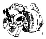 figure 1)
- the length of this hose varies from 6" to 4' depending on your car manufacturer and whether or not an intercooler is fitted. you should locate the splice in this hose as far away from the turbo heat as is practical. (read optional note before cutting this hose as it may affect where you cut this hose.) on some cars this is a metal tube rather than a hose. (volvo owners with factory intercooler need to read optional modifications here.)
- cut hose and install 'T' fitting with host. fit tie-wraps on both hose ends you push on. (see
 figure 2)
- route hose away from hot exhaust system components and away from any moving parts (i.e. steering linkage, throttle, fan belts). leave hose full length before test driving.
- TEST DRIVE. warm up engine before testing for boost pressure. drive until temperature gauge registers in the normal range. to measure boost pressure, place gear selector in 2nd or 3rd gear, depress throttle all the way (WOT) - unless you have an automatic, in which case don't depress far enough to engage the kick-down - and simultaneously apply the brakes to maintain 2500-3000 rpm. read the boost pressure. you don't want to do the above procedure very long as the brakes can overheat.
- compare present boost pressure with pressure BEFORE installation of kit. (why didn't they put this above, before step #1?) (at this point we must point out that it is best to have a gauge that reads out in PSI or BAR. your readings will be more accurate than with the factory-type high-low gauges. VDO #9B2500 will fit in stock dash location of '82+ Volvo 240's.
- to increase the boost pressure simply shorten the open end of the hose. it is recommended that no more than 6" be cut off at any one time.
- please note that you are limited as to how much you can raise the boost pressure because the car is usually setup with a fuel pump safety cut-off switch. this switch can be set at any number of settings depending on how the car was equipped from the factory. early Volvos without factory intercooler were usually set at 10PSI while intercooled models were set at 14PSI.
- to reset the fuel pump safety cut-off switch, find its location. (on Volvo models it is usually on the foot pedal bracket - inside the car.) if you can't find it or don't know where to look, you can usually trace the few pressure lines from the intake manifold and find the pressure switch. (NOTE: the cut out switch for the A/C is the same type but usually located on the fender well. (see
 figure 3)
- the arrow in figure 3 is pointing to the factory seal that prevents changing the preset pressure. to change it, all you need to do is dig out the epoxy seal with an awl or sharp instrument, or squeeze the rim around the seal with pliers or vise-grips to break it loose. once the epoxy seal is removed you will see a recessed screw for adjusting the pressure shut-off point. to raise the shut-off pressure, back the screw out. (without a measured source of pressure all you can do is guess how far to back out the screw. on Volvos, flush with the top usually is about 14PSI.)
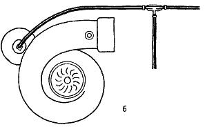 figure 4 shows a finished installation. it is only intended to give you an idea of general proximity of parts. (shown as if on an intercooled car. non-intercooled models would probably have a hose coming from location arrow indicates.)
when this kit is installed and functioning properly, it is normal for there to be a slight hissing sound when operating under boost. depending on the car and noise insulation this may annoy you. if it does (or if you want to avoid it) you can perform a minor modification to cure it.
simply drill a hole in the intake system ahead of turbo but after the air cleaner. stick the end of the hose into the hole and the hissing will not be audible.
check the hose outer diameter - it will usually be 3/8" OD, in which case a 11/32" hole will hold the hose snugly but not interfere with pressure escape.
- Volvos with overboost indicator light:
this light may be deactivated by disconnecting the blue wire coming from the factory boost gauge. if you replace the gauge with a VDO or other make, you will by necessity have to disconnect the light. insulate the wire end with tape.
- Volvos with RPM limited boost relay:
intercooled models come from the factory with a relay that restricts the amount of boost pressure in the lower rpm's. you can gain a significant amount of low-end torque by increasing the boost at the lower rpm. all that is necessary is to bypass the relay (on/off valve) and operation will be like our boost+ kit. use an appropriate length of hose to eliminate the on/off valve.

ADDITIONAL INFORMATION:
since different manufacturers reference different measurement standards, here is a table for a rough cross-reference.